| Section Page | Previous Page | Next Page |
Clutton's signal construction and operationby Tim VentonThis page describes the construction of signals for Tim Venton's Clutton
Construction
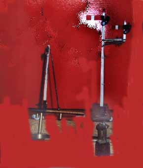
First I wanted to produce all the posts, for which I had adequate details of the dimensions. There are whitemetal posts available, or some modellers use plastic but I chose brass. The technique used was to take lengths of square section brass (5/32" or 3/16" as appropriate), each an inch or so longer than the finished post. Each length was bolted in turn to a strip of 1" by ¼" steel strip, which could be firmly clamped in a machine vice bolted to the cross slide of the Unimat (lathe). A dial gauge was used to drop one end to set the taper to the amount of 1 in 60. Several attempts proved necessary to set the correct angle, but once established, all posts could be cut without further adjustment, because all GWR wooden signal posts were sawn to the same taper, irrespective of height. Thus, the taller the post, the wider the base in proportion, which would be necessary to give the post sufficient strength. Incidentally, in the Adrian Vaughan's OPC book mentioned, this taper is stated to be 1 in 5, which is a misprint, as it should be 1" in 5' (1:60). I used a slitting saw mounted in the milling attachment to slice off the scrap from the bar stock. The workpiece fed across the saw, using the cross slide feed-screw, with the top-slide feed screw set to make only a very shallow cut at the near end of the post. Alternative movements of cross-slide and top-slide feed-screws then followed, so that slightly more metal was removed each time the post was fed across the saw, always cutting only when the post moved away from the operator. Only very light cuts could be made, otherwise the workpiece would whip about, causing irreversible damage. When the machining extended over the length of post to be tapered, the embryo post was removed from its supporting steel strip 'jig', the taper checked with a vernier and, if satisfactory, the post was bolted back on the jig 90° from its original position and the second face of the post similarly treated. After yet another check with the vernier to ensure that the correct thickness had been achieved, the post was removed from the jig. After machining had been completed, but before cutting to length, the marks left by the saw were removed by filing each post with a sideways movement, using a smooth No 4 file. The signal arm spindle bearing is next to be made, which is a fairly substantial and complex casting, and in model form, fairly difficult to reproduce. The pictures of Newbury bay starter show the appearance. I therefore compromised by making bearings from short pieces of 1/16" brass rod, which were drilled in the lathe to suit the wire I intended to use for the spindle. The undrilled length was then used to hold each piece whilst 'flats' were filed at the drilled end to produce a square shaped section. This was cut into lengths slightly longer than the width of the top of each post and soldered in position. Note how far the signal arm and backlight are from the post, and file to that size. A slot is cut through this pivot with a file, then the top and bottom extensions were made from plasticard, glued on with super glue. Construction then proceeded as follows. After machining and filing, the posts were cut to length and a pilot hole drilled in each end. That at the bottom was opened up with the appropriate drill to allow it to be tapped 8BA. That at the top was later opened up to suit the finials. This hole was drilled 1.5mm. All posts were then drilled to take the spindle for the counterweight arms and then fitted with brackets. These were tiny exercises in milling in the lathe that I won't go into, pictures of the prototype were my inspiration. Base plates were next cut from 1/16" copper clad sheet, the length in each case varying, but such that the front edge would be 10mm in front of the centre line of the post and the rear edge coincided with the bottom of the ladder. Thus the latter could he safely soldered to the base plate in due course. Each base plate was drilled and countersunk on the underside to take the 8BA screw and then firmly attached to its post by means of a short 8BA countersunk screw. The bracket supporting the doll for the subsidiary arm of the up main home signal was made from 1mm brass section over a plan, to ensure they were identical. Counterweight arms were next made, I used some from a Sprat and Winkle etch, with slices of turned 1/8" brass bar, slotted to fit over the etch. Neater than soldering on small pieces. Finally turning to the arms and blinders, I was fortunate in having a supply of Colin Waite items, easily the best. These were cut from the etched sheet and cleaned up. The arms were each soldered to a pivot rod. One modification was to put a limit stop onto the back of the arm. This ensures the arm always returns to the correct angle. It is even possible to put the characteristic slightly high arm, where the stop spring has worn. They were primed and painted. Glasses were applied by taking an idea from Peter Squibb, applying cellotape behind the spectacle plate, with the coloured acetate pressed onto the front. They were not finally fitted until work on the operating mechanisms had been completed, to avoid accidental damage to the arms. Framework for the platforms was fabricated from fine wire, some of it square in section, and fine strip, but at this stage the timbering was omitted to facilitate painting. Subsequently, timbering for the bracket signals was cut from 0.4mm ply, from an aeroplane modeller's shop. Ladders were assembled from Colin Waite components, still the best, but sadly unobtainable. They are very difficult to assemble, those who have these kits should know how, so for you dear reader if you have got this far, I will assume that you have a more modern kit, so will use that instead.
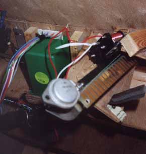
Making the signals work
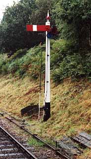
What about the bouncing signals? Standard Great Western lower quadrant signals bounced, by nature of the stretch in the wire making them over pull on the downward stroke, then on their return to danger, there was a spring loaded stop. A worn spring would give that characterstic arm at on but pointing slightly upwards.
|
| Section Page | Previous Page | Next Page |