| Section Page | Previous Page | Next Page |
N30 10-ton Loco Coal Wagonby David Pearce
|
| These wagons, which were introduced in 1935 (the instructions say 1930), were the final GWR design of small capacity locomotive coal wagon. The design of small locomotive coal wagons had evolved over time, in line with the evolution of other types of wagon. The N30 featured Morton brakes, square corners on the body, and were 21'6" long on a 9' wheelbase. There were no door springs, as had been seen in previous designs. N30 wagons, in common with older small capacity locomotive coal designs, would have been included in long distance freight trains between the coalfields and major freight yards. They would, however, also have been in local and branch trains as their main role was delivering coal to local locomotive depots, including the small outposts where there might have been only a single engine. |
 |
Cambrian kit
The Cambrian C2 kit has been around for some time. The particular example used for this project was quite elderly. As with many plastic kits this one is supplied as as a set of mouldings. There were four sprues and a separate floor moulding. Extra parts are supplied with this kit, which is a useful source of spare parts for other projects. As is normal for Cambrian kits, wheels and bearings are not included, and a short piece of 20 thou plastic rod will also be required. Scale couplings can be fitted, and an adapter to allow Hornby type is included – the actual couplings will need to be sourced separately.
As usual for Cambrian kits, the instructions are brief (the text of instructions issued with newer kits appears to be the same as older examples, but new typesetting has greatly improved their clarity).
Construction
| Construction starts with the running gear. After separating the W-irons, axle boxes and solebars from the sprue, some cleaning up will be needed. According to the instructions the builder locates the axle bearings in the holes in the W-irons, and attaches the axleboxes to the rear. When this was attempted with waisted bearings there was too much slop, and shouldered bearings were found to be a better fit. It was, however, a bit fiddly to get the axle boxes to line up correctly; they need to be vertical and line up with the shackle on the leaf spring (which is on the W-iron moulding). If the model was being built with a compensated or sprung chassis, this design might be a considerable aid to the modeller. |
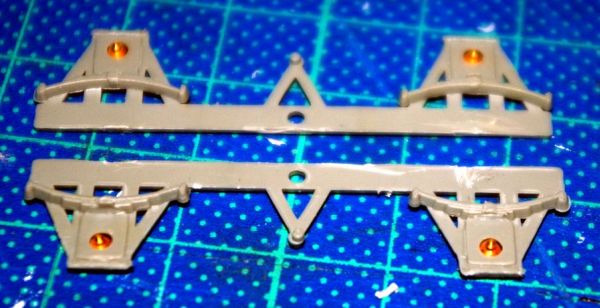 Wheel bearings inserted into the W-irons |
| The next stage is to attach the W-iron mouldings to the back of the solebars. The solebars have a circular pip lining up with a hole in the bar at the top of the W-iron mouldings. The top edge of the solebar and W-iron units may need some cleaning up with a file.
The solebars can now offered up to the floor. I found that the solebars were longer than the floor. I trimmed the length, but it is important to make sure that the axles will be parallel and equidistant from the centre line of the floor. Later in the build I realised that trimming the solebars was a mistake – the body fits around the floor and the headstocks should be a little clear of the end of the floor. |
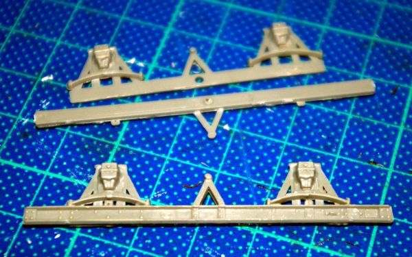 The W-iron units are attached to the back of the solebars |
| The headstocks are tackled next. The instructions suggest that scale couplings should be fitted to the headstocks at this point. In order to fit the scale couplings I was using it was necessary to slightly elongate the hole for the coupling hook to pass through, however care is needed as the enlarged hole significantly weakens the headstock.
After attaching the headstocks to the ends of the solebars, I fitted the buffers. There are small collars that fit onto the buffer shanks. The collar is threaded onto the buffer shank and then the buffer shank is inserted into the buffer housing moulded on the headstocks. |
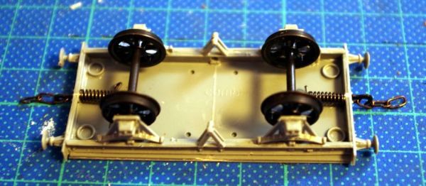 The assembled underframe before the brake units are fitted |
The body consists of four parts, two sides and two ends. These are assembled around the floor. On the inside of the body parts there are ridges, these should fit against the floor, not sit on top.
These wagons were fitted with Morton brakes, but brake rigging only on one side of the wagon. The kit is designed with locating pips on the brake rigging unit, these are supposed to fit into holes on the underside of the floor. Two sets of two brake rigging units are supplied with the kit. The units on the underframe sprue appear to be for DC brakes, those on the body sprue are the correct units to use (but only one is used).
| I found that the holes were too far from the solebars, and that the brake blocks fouled the wheels. To correct for these problems I removed the locating pips and positioned the brake rigging unit by hand. I also needed to file the back of the brake blocks to ensure the wheels would turn freely.
The two brake levers are the next parts to be fitted. These needed some slight cleaning up. Finally a piece of plastic rod is fitted between the V-hangers and the back of the pivot in the rigging units. |
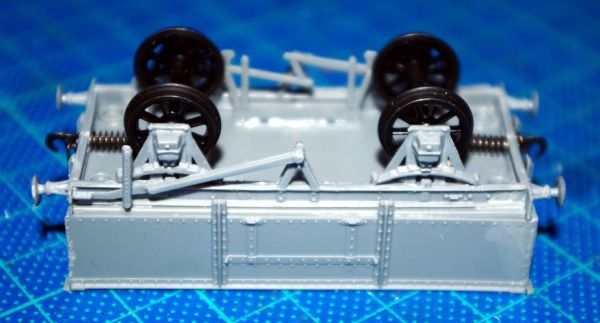 The fitted brake levers, with the rod connecting both sides of the brake gear still to be added |
| Section Page | Previous Page | Next Page |