| Section Page | Previous Page | Next Page |
Farthing: The Bayby Mikkel Kjartan
"The bay" constitutes the first step in a long-term modelling project. The idea is to overcome the constraints imposed by my very limited modelling space, without giving up my ambitions of modelling a fairly large station. Essentially, I plan to build a series of minimum-space layouts, with each layout representing one small section of the same mainline through station. In other words, I plan to eat the elephant one bite at a time. Each layout will be self-contained and modelled and operated in its own right. The individual layouts will never exist at the same time, and hence can never be connected in reality. But in my mind, they all form part of the same station. Each layout must follow the same set of core principles:
The layouts will all be set during the years 1904–1908, with some allowance for running later period stock when no one is looking. Apart from "The bay", I currently envisage subsequent layouts depicting Farthing's Loco shed, Goods yard and Carriage sidings respectively. That should keep me going for a few years!
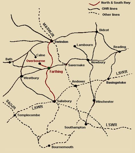
A place called Farthing "The bay" represents one of the bay platforms at Farthing, a fairly large junction station at the intersection of the Berks & Hants line and the old North & South Railway. As most will know, the N&SR sought boldly to connect Swindon and Bournemouth, and thereby link the Midlands and the North with the "Gold Coast" in the South. In the event, the line never actually made it further than Salisbury, facing tough opposition from the combined forces of the L&SWR, the S&D and the M&SWJR. The line thus suffered much the same fate as the D&NSR further East, ending up as little more than a cross-country route linking Swindon, Farthing and Salisbury. In 1891, the line was taken over in full by the GWR.
The N&SR did however place Farthing firmly on the map as a fairly significant junction station, strategically located between Newbury and Westbury on an East-West axis, and Swindon and Salisbury on a North-South axis. Apart from this, Farthing was also the starting point of the local branch to Overbourne, market town of the Barrow Downs and a much favoured training ground for race-horses. Much like the Lambourn branch departing from Newbury, the Overbourne branch was developed fairly late in railway history after several abandoned schemes. Apart from local passenger services, the branch profited reasonably from the carriage of milk to and from the rural farming communities North of Farthing, and the carriage of horses to and from the extensive training grounds around Overbourne. "The bay" depicts the Overbourne bay at Farthing, in the period 1904–1908.
This is all fiction, of course. I prefer modelling fictional locations, but I like to provide a larger context for them, and to weave them into the real railway landscape of the time. I feel this helps define the scope and nature of the layout and its operation. So there was never a station named Farthing, nor a line named the N&SR. Instead I draw heavily on nearby Newbury and its railways as a source of inspiration – including of course the DN&SR and the Lambourn branch. Incidentally, the fictional place names used here are all borrowed from Tolkien – who, it seems, was himself inspired by this part of England. His map of "The Shire" even includes a "Newbury"...
The bay concept
I have always been fascinated with the many bay platforms employed on the GWR, usually serving branches, but sometimes also cross-country lines. From a modellers point of view, such bay platforms provide several of the useful characteristics of branchline terminii, while at the same time giving scope for something a little different. For one thing, the bay platform arrangement is particularly well suited to minimum-space layouts: Since bays often contain little more than a single running line and a siding or two, they allow for a trackplan that is both prototypical and feasible within a small space, without being overly cramped. Apart from this, bay arrangements provide an excellent opportunity to model part of a larger station in a small and self-contained area. Here you can have your built up / urban setting while still enjoying the benefits of a small terminus-type trackplan.
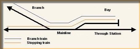
Moreover, the location at a large station justifies a wider scope of stock and operational potential than would be seen at a branch terminus: Suddenly you can include features such as station pilots, "strengtheners", and even local main-line stopping trains departing from the bay. The diagram below shows the overall arrangement upon which operation of "The bay" is based. The bay platform (top right) serves the branch to Overbourne (top left), as well as a local stopping service along the Down Main. The arrangement is inspired by the Winchester and Lambourn bays at Newbury. The location of the bay on the Up side emulates the Lambourn bay, while I borrowed the idea of the local stopping train from the Winchester bay, which apart from the Winchester line also served local stopping trains for Westbury.
The branch train travels continuously along its own metals (as on the Lambourn branch), but the Down stopping train crosses over the Up Main before reaching the Down line. While not unheard of in the real world (Wrexham and Avonmouth are examples), this is a complication that could be avoided – all you need is to switch the bay to the Down side.
Shades of Newbury
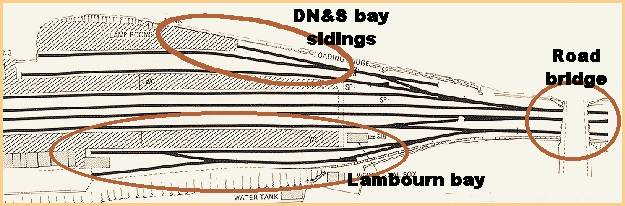
Although the layout is based on a fictious location, I wanted the trackplan to draw on prototypical elements. Again, Newbury station was the main source of inspiration, with no less than three bay platforms to choose from – i.e. the branch bay to Lambourn and the up and down bays for the Didcot, Newbury & Southampton line (see the GWR Features section for more about the DN&S). The Lambourn bay was no doubt the most typical of these, comprising as it did a run-round loop and a singular short siding. The down DN&S bay was rather more elaborate, including a loading dock for horse traffic, a goods siding (later complemented by a carriage siding) and a short spur (originally used for a small turntable).
Given the space available, I decided to draw loosely on the Lambourn bay arrangement, but with the addition of the horse dock and goods siding from the Winchester bay, so as to increase operating interest. A road overbridge near the two bays was also incorporated, in order to provide the usual break between the scenic and non-sections. The Didcot Bay at the other end of Newbury station (not illustrated) also provided inspiration: Here, the bay platform extended benath the overbridge, providing a good excuse for what would otherwise be a rather short bay platform.
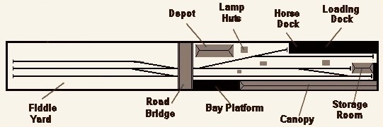
The full trackplan is shown here in schematic form. In order to save space, the run-round extends onto the fiddle yard section of the layout. The fiddle yard itself is an utterly simple three-road affair, but is nonetheless crucial to operation of the layout, since virtually all stock movements on the scenic section need to go via the fiddle yard. For this reason, I decided not to employ a sector plate or casette arrangement, as this would have led to constant messing about in the fiddle yard whenever a move was made on the layout. Instead, three motorized points are used, allowing for a more continous flow of train movement. This is complemented by a modified Peco Loco Lift when loco release is required.
Baseboard in a box
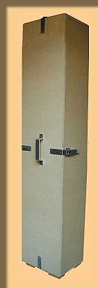
The layout has to be stored in our basement locker room when not in use, so I decided to nest the baseboard permanently within a box-like structure. This provides protection from damage and dust during storage, allows me to carry the layout like a suitcase, and allows for easy storage in the vertical position. This has proven quite effective, and when stored the layout takes up very little space.
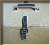
The baseboard itself measures 32 x 165 cms (that's 12.6 x 64.9 inches), with the full boxed-in structure amounting to just a couple of centimeters more in length and width. The box is built from 9mm and 16mm chipboard variously, with plywood along the front of the baseboard for aesthetical reasons. Chipboard is not exactly state of the art, I know, but I had some lying about anyway, and I was anxious to make the box as sturdy as possible. I must admit, though, that the whole thing has turned out even heavier than I had expected. Still, I can carry it by myself as long as I eat my spinach! When the layout is in use, the front and top boards of the box are simply removed and put aside. I did consider making them hinged, but decided that this would be impractical and visually unsatisfactory. Instead, the removable boards are fastened with a simple yet very efficient type of draw-latch (as used on tea chests and the like).
For operation, the box is simply placed on two foldable trestles, giving a height of 85 cm (33.5 inches) above floor-level. This is an ideal height for relaxed operation when sitting down (my kind of armchair modelling!), and also allows standing onlookers to bend down lightly to view the layout at eye-level.
Getting wired
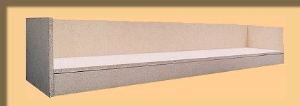
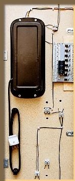
It was important for me that the electrics were fully contained within "the box". All electrics are therefore fixed to the underside of the baseboard, and all that is needed to get running is to plug in the mains cable. There is no actual bottom to the box, allowing easy access to the wiring etc. In fact, wiring up the layout was almost a joy this time, since all I had to do was stand the layout on its end. The transformer and Point Control Unit (PCU) are enclosed in protective covers – well, baking tins actually!
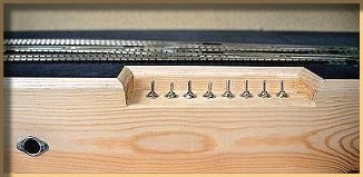
The wiring itself is as simple as can be, using simple dropper wire soldered at intervals to the underside of the rails. In order to maintain some degree of neatness, the dropper wires and point wiring are fed in to individual terminal blocks, screwed to the baseboard underside.
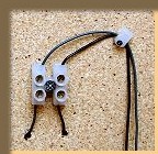
Points are Electrofrog, driven by Peco motors through sub-baseboard extension pins. I have always found the Peco motors very reliable and have yet to experience a burn-out. The points themselves do need a bit of preparation, though: As they come, the plastic toe of the frog sometimes stalls kit-built short- wheelbase locos with finer-scale wheels, by lifting them ever so slightly off the track. I find that careful work with fine grade sandpaper usually levels out the toe and eliminates the problem. An 8-switch AMR PCU has been recessed into the front of the baseboard, including a self-contained Capacitor Discharge Unit (CDU) to feed the points adequately.
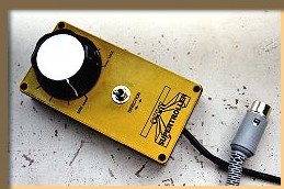
Each point is thrown independently. I could have connected them, but I rather like operating the points and making sure the road is set as it should be. I use a handheld Orbit controller, which plugs into an outlet in the side of the structure. It provides for some very smooth running, but Orbit are unfortunately no longer on the market. The transformer is a standard Gaugemaster item.
Down to basics
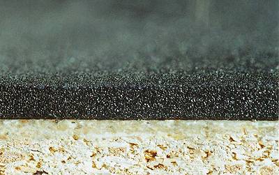
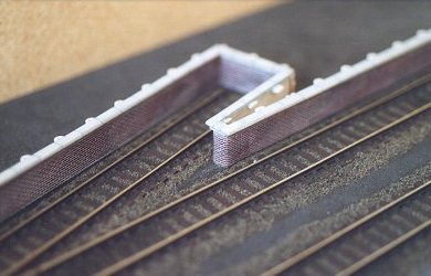
When building a layout, I like to work with a small "test-board" on which I test out techniques and materials before using them on the layout itself. Here's a description of my experiments with underlay, track, ballast and surface texture, with illustrations from the test-board. Underlay Inappropriate running noise is a big issue with me, and I was worried that the chipboard structure surrounding the baseboard might act as a giant loudspeaker. I therefore wanted something even more sound-deadening than the usual cork underlay. Carpet underlay has been used successfully by others, but I was unable to find anything sufficiently smooth. Eventually, the neoprene underlay from C&L Finescale proved a good solution.
The C&L foam may at first seem rather sensitive: Even a light prod of a finger leaves a noticeable hollow. However, the foam eventually evens out, and in any case becomes much less sensitive once fixed in place. For this I used a gooey, water-based glue, normally applied to carpet underlay. The track in bay platform areas was often level with the ground, and so I wanted to avoid the usual shoulder of ballast. I therefore decided to extend the foam across the entire baseboard, rather than using it only beneath the track. This also allows buildings and structures to be recessed into the foam by cutting appropriate holes, thereby eliminating the problem of unsightly gaps between structures and ground surface.
Track The track is Peco Code 100, left over from an earlier layout. I consider this a compromise, but I stuck to my principle of exploiting the items I already had available. Moreover, with careful ballasting and weathering it is a compromise I can live with. I did experiment with the sleeper spacing, to see if I might create the illusion of scale track gauge. To do this, I cut away the connecting plastic strips between each sleeper, allowing me to position the sleepers at will. However, comparison with prototype photos suggested that even the visually most optimal spacing gave a slight narrow gauge look. There was also the prospect of undertaking this rather fiddly exercise on the pointwork, the thought of which was not alluring. I therefore decided to retain the factory-made sleeper-spacing and focus on making a decent ballasting and weathering job instead.
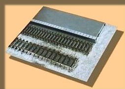
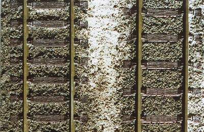
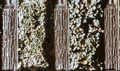
Ballast In Edwardian times, neat ballast shoulders were rarely seen in bay platform areas. Indeed, photos of the Newbury bays suggested a light sprinkling of a rather fine ash-like ballast, and sleepers almost level with the surrounding ground. Since most manufacturers seem to insist on over-scale ballast, I experimented with both 2mm stone ballast and ash ballast. In the end I opted for Carr's Ash Ballast, a dark grey matter of fine, non-stone material. This is, I think, a little too coarse for actual ash in 4mm scale, but gave a nice representation of the very fine ballast I was after. The picture above illustrates how it compares with Carr's 2mm Dark Grey Ballast. I applied the ballast to the track through a film cannister, pierced with holes at the bottom to get an even and controllable spread. This was then adjusted with a fine brush and a not-so-fine index finger. The ballast does not seem to come to any particular scale, and the grains themselves are of slightly different sizes. I therefore found it prudent to sieve away some of the finer dust beforehand, and then later add it to the top of the coarser ballast in order to enhance the "fine" look. Glueing of track and ballast followed the usual routine of water and PVA.
On the whole I found the results reasonable. Weathering is required of course, especially since the dark grey develops a slight green tint once fixed in place. Incidentally, the jar of ballast includes a small bag of lighter material for simulating fresh ash or creating lighter patches. This is of a different material and frankly didn't work for me – it looked as if someone had spread white 4mm flower petals everywhere!. But maybe it's just me.
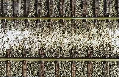
Ground texture The bare ground that is often found in bay areas and along sidings is essential to get right, and yet, I find, is also among the most difficult textures to achieve. Here I reached back to my diorama modelling days and used a simple yet effective mix of polyfilla, PVA glue and water. The exact proportion of each can be varied according to the degree of roughness wanted (indeed, that is part of the point) but I usually find that 1/3 of each is a good place to start.
It is best to use the rougher type of Polyfilla (intended for outside applications), as the finer variants tend to produce an overly smooth texture. The Polyfilla mix is applied with a brush or a broad piece of Plastikard – or whatever else can help give the desired texture. While the mix is still wet, I then use bits of card etc to smooth out or roughen up the ground further. The trick is to avoid things getting too coarse, and yet incorporate the subtle variations that makes it all look real. I sometimes sprinkle on dry polyfilla through a sieve immediately after applying the main mix, thereby adding a subtle coarsenness to the ground. When working next to trackwork, a very thin mix is brushed around and slightly into the edge of the ballast. This helps create the gradual, almost un-noticeable transition from ballast to plain dirt so often seen around sidings.
Platforming
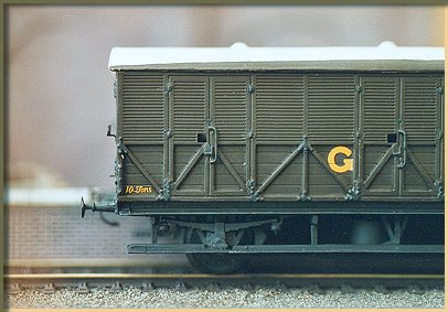
The construction of platforms and loading docks on layouts are rarely described, perhaps because it is usually a fairly simple task. Yet surely platforms have a very significant visual impact on layouts, rather like the lines, breaks and angles that structure a painting. The platform The main bay platform runs along the full front of the layout as both a natural barrier and an indication that we are seeing just one part of a larger station. This arrangement also allows me to see my stock arriving and departing with wheels and underframes hidden by the platform. This, I find, adds depth and helps create an illusion that we are standing at ground level watching the trains come and go. The main platform was built using adapted Peco platform sides and edging, faced with brick-pattern Plastikard from Slaters. The surfacing is Wills Victorian stone paving, cut to shape and mounted between the Peco sides. I have always rather liked this kind of paving, which was used on the Newbury platforms and, of course, many other locations.
The Loading Dock The Loading Dock is at the back of the layout, and also adds a certain depth to things as it is relatively wide in places.
The dock uses the same sides as described above, but for the surface I wanted to capture that cinder-look which is apparent from so many period photos. Drawing on Stephen William's "Great Western Branchline Modelling", I used very fine sandpaper painted and rubbed with light earth colours. In the end this did give the desired effect, although it required some patient working with paint and texture to get it right. Also, you need big sheets of sandpaper to avoid joins! The sandpaper is glued to a thick sheet of Plastikard, and rests on supporting cross-members. No doubt some would have preferred more curved platforms and track, as yet another means of adding depth and interest to the layout. However I frankly rather like straight lines – although I did try to break the geometry a bit when designing the Loading Dock.
I Think I Canopy
The canopy uses heavily modified parts from a number of Ratio Platform Canopy kits (purchased cheaply on ebay), combined with a few bought-in extras. This page describes the key features in this fairly simple conversion project. Roof and skylights
The skylights on the Ratio canopy sections are spaced at intervals, whereas many (though not all) GWR canopies seem to have had continous skylights. I wanted to capture this latter feature, and so cut up the Ratio roof sections [see photo] and joined the modified sections to form one long continous skylight. The Ratio skylight frames furthermore stand proud of the roof itself, whereas most GWR skylights seem to have been level with the roof. This was solved by overlaying the modified roof sections with an extra roof layer (cut from other, abandoned roof sections), thereby levelling the height difference between skylight and roof. This also allowed the rather narrow roof to be widened.
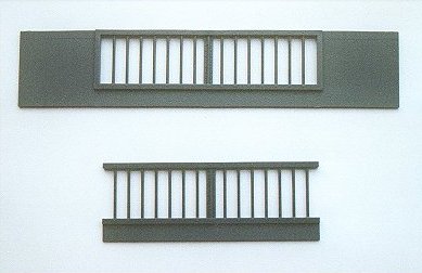
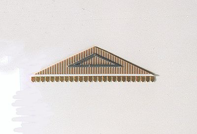
End sections The original Ratio end sections are rather plain, and were replaced with new ones knocked up from bits of plastikard. For decoration, I chose the simple triangular panelling used at a number of GWR stations. Valancing The valances are etched brass examples from Muswell Models, replacing the rather crude versions that come with the Ratio kits.
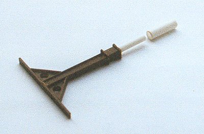
Canopy supports The Ratio canopy supports are a fair representation of a widespread design that was also used at Newbury, so these were built as supplied, but with a section of plastic rodding built into the base (see photo). The plastic rods slide into slightly larger plastic tubes fitted beneath holes in the platform floor, thereby providing a tight fit while still allowing the canopy to be removed during transport or storage.
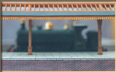
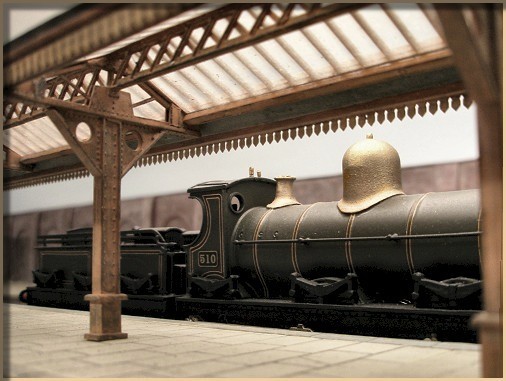
Positioning My logic behind placing the canopy at the very front of the layout was to force spectators to look beneath it – rather than over. This adds depth to an otherwise quite narrow layout, and provides for nice ground-level view of trains as they arrive and come to rest beneath the canopy.
Although much remains to be done on the layout, the visual outlines are beginning to emerge. I do need to tone those stone colours down though, so the canopy can blend in better with the general colour scheme. So back to work!
Structuralism
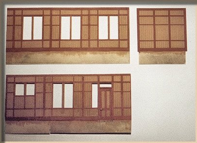
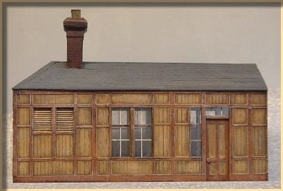
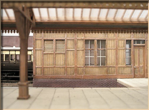
The past year has been a busy one for me, and so progress on "The Bay" has been limited. However, I did manage to get some work on the main buildings done: Waiting room The Lambourne Bay at Newbury featured a fairly substantial brick-built storage room at the beginning of the bay platform. In layout-terms, the position of this building provides several benefits: it hints at the larger station buildings beyond the layout, and partly blocks the view of the siding and loading dock behind it, thereby adding to the three-dimensional feel of this quite narrow layout. The building also gives further reason for the viewer to look beneath the canopy, which is a main concept of the layout.
This was done quite simply by scoring the cut-to-shape plasticard sides and ends of the building to emulate the plankings, and then adding strips of further plasticard to give the panel effect. The roof is made from card strips. These simple techniques were copied from an old second-hand building I picked up a while back and were fairly quick to carry out.
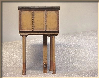
Water tower The water tower is based on a rough and simple design that was widespread on the GWR. A similar design (although of a larger, six-legged variety) was found in the Lambourne bay area at Newbury, where it served the platform water bowsers from an elevated position.
The model was put together in an evening from bits and pieces from my scrap-box, including Ratio parts for the tank itself. I rather like these simple little projects, which contribute nicely to my objective of using mainly existing or leftover parts, while still drawing on prototypical features.
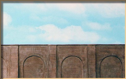
Embankment walling For the brick embankment walling I thought I'd experiment with some new options and used the vacuum formed plastic walling available from Langley. This is preformed and comes with four bays in each section.
To be honest I am somewhat ambivalent about this product. On the one hand it is very lightweight and can be mounted with quick results. On the other hand the brickwork lacks the sharp crisp edges of plastic kits, which can be dissatisfying when viewed close up. Also, the bottom edge of the walling needs to be cut off, which in this case is difficult to do neatly as you are not working with a flat object. To cut a long story short, on this particular layout I think it works out OK as the walling is at the back, but it may not be the best choice for embankments that are more visible at the front of a layout.
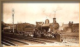
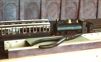
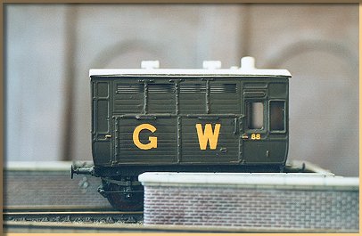
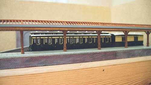
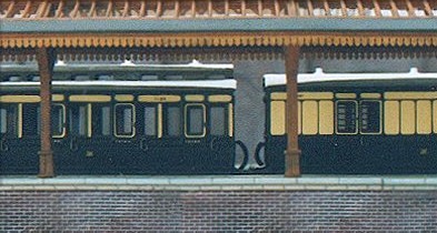
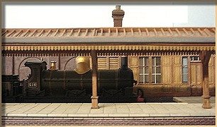
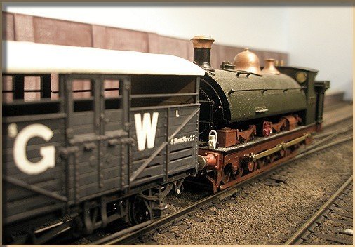
Progress pictures Although the layout still lacks all the detailing, weathering etc it is fully operational and trains run regularly, so I couldn't help putting up these shots that hopefully hint at the atmosphere I'm trying to create.
Mikkel's Farthing photostream on flickr. |

| Section Page | Previous Page | Next Page |